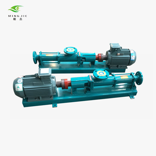
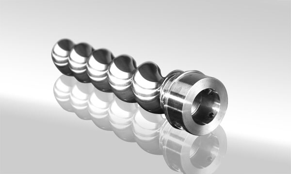
The primary elements that constitute the three-screw pump are the bushing (pump cylinder), which is secured within the pump body; a driving screw; which is inserted within the pump cylinder; and two driven screws; which mesh with it. All of these elements work together to create the pump. This cavity is likewise hermetically sealed off from the surrounding atmosphere. The pump is able to function in a manner that is more efficient as a direct result of this fact. Furthermore, there is no bending load because the radial force exerted by the driven screw is supported along its entirety by the pump cylinder bushing. An oil film will form during operation between the outer surface of the screw and the inner wall of the pump cylinder. This will allow for smoother operation. This oil film has the capability to prevent the metals from coming into direct contact with one another. As a result, the amount of wear that takes place on the surface of the screw teeth is significantly reduced.
The suction and discharge pressures of the liquid act on the two ends of the screw pump during operation of the pump in such a way that the axial thrust is generated on the screw. If the differential pressure can be kept at the same level, then smaller pumps with a differential pressure of less than 10 kgf/cm2 can make use of thrust bearings. However, this requires that the differential pressure food grade pumps be able to be maintained. In addition to this, the driving screw has a central oil hole that enables high-pressure oil to be pumped through it and into the bottom of each screw bushing. This is possible because the driving screw was designed with a central oil hole.
If the pump discharge port is completely blocked off, just like it is the case with other types of positive displacement pumps, the internal pressure of the pump could reach an unsafe level, which could either cause the pump to break or overload the motor. This situation is similar to the situation that occurs when other types of positive displacement pumps are used. As a direct result of this, it is necessary to install a safety valve in both the suction port and the discharge port of the pump. The shaft seal of a three-screw pump typically consists of a mechanical shaft seal; however, this seal can be adapted to a variety of configurations in accordance with the working pressure. Working pressure refers to the amount of pressure that the pump is designed to withstand.
The following is a list of distinguishing characteristics of a three-screw pump:
There is no variation in volume during the time that the fluid in the pump is being actively pumped, and the Rui flow is not subject to any stirring or pulsation during this time. When convection is taking place, the volume cavity that is produced by the elastic stator has the potential to significantly reduce the amount of wear that is taking place as a direct result of the convection process.1. As a result of this, the pump now has the capability to carry out the duties of an isolation valve.2. It is capable of multiphase mixed transportation of solids, liquids, and gases in all three phases simultaneously.3. 5. The viscosity of the input medium can reach up to 50,000 MPas, and the percentage of solids can reach up to 50,000 percent.7. Depending on the circumstances, the pump can be used to move in either a positive or a negative direction.
The utilization of a pump that is composed of three screws is connected to a variety of benefits, some of which include the following:
1. 2. In comparison to the plunger pump, the screw pump has a greater capacity for self-priming and a stronger suction height;
3. The three-screw pump, in contrast to the gear oil pump, has the capability of transporting substances with a high viscosity;5. In contrast to plunger pumps, diaphragm pumps, and gear pumps, screw pumps are well-suited for use stator manufacturing in the pharmaceutical industry due to the fact that they are suitable for use in both vacuum and pressure applications.
The pump is violently vibrating, the electric rotor may be unbalanced, or the coupling may be poorly combined, and the bearing may be worn and bent; it is also possible that some rotating parts are loose or broken; perhaps the pipeline support is not as strong as it should be, etc.; the pump may have other issues as well. Adjusting, fixing, reinforcing, and replacing components are all viable options that can be pursued, in addition to a vast number of other potential courses of action that could be taken.
It is possible that the nut was not tightened sufficiently when it was being installed, which would explain why the pipeline is leaking. Another possibility is that the nut was not installed properly. There is also the possibility that the nut was not fastened in place correctly. In the event that water seeps out of the joint, the nut can be tightened by hand in order to stop any additional water from escaping. It is necessary to disassemble the system whenever there is a significant amount of water loss.
Magnetic pump with overheated packing, most likely as a consequence of the packing having been packed in an excessively tight manner, the cooling water being unable to enter the packing, or the packing's shaft surface having been damaged. It is an absolute necessity that old packing materials be replaced with brand-new stainless steel food grade pumps materials as soon as possible. In order for it to be installed, first it must be lubricated with oil, and then it must be turned in circles while being loaded. After the final round of packing has been installed, the gland needs to be tightened, and then the level of tightness needs to be adjusted while the machine is running. This process should be repeated as necessary.
The water pump may be unable to absorb or drain water for a variety of reasons, the most common of which are that the bottom valve is stuck, the water filter is partially clogged, the water absorption height is too high, or that the water is leaking. Other possible explanations include: the water is leaking, the water filter is partially clogged, the water absorption height is too high, or the bottom valve is stuck. However, the issue may also be the result of improper steering or the obstruction of the flow channel in the impeller. Both of these possibilities are also possible. The subsequent steps, which may include repairing the bottom valve, removing the silt, adjusting the steering, and cleaning the impeller, may be taken after the individual components of the inspection have been successfully completed in turn. The inspection is finished when each individual part of it has been carried out successfully and the whole thing has been looked over.


